RESOURCES
Powering Beam Steering with DC Current
Particle beams are utilized in diverse applications such as Ion implantation techniques for semiconductor manufacturing and proton therapy for the treatment of cancer cells in the body. These beams require the use of large DC electro-magnets that generate strong magnetic field vectors. Magnetic vector fields are used to steer particles in three-dimensional spaces towards a specific target. The magnitude of DC current supplied to the magnet coils controls the field strength, which is then in turn used to control beam deflection.
The coils of large DC electro-magnets are highly inductive in nature and pose challenges to power conversion equipment being used to provide DC current to the magnet. Inductances in the range of 4mH are not uncommon for this equipment, and DC currents in the range of 100A DC to 1000A DC.
The Importance of Current Precision in Beam Steering
Figure 1 provides an illustration of the concepts of accuracy and precision. Accuracy can be defined as how close to the desired parameter is a piece of equipment capable of achieving. For beam steering purposes, this can be considered how close to a desired current the power supply can be programmed.
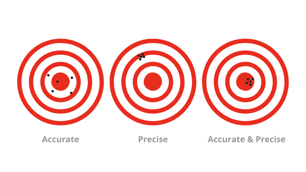
Figure 1 - Accuracy and Precision Model
Precision can be defined as how repeatable a given result is. For beam steering purposes, this can be considered as how tightly grouped the results of programmable current are for the same programming input.
The technologies that utilize magnets generally require a high degree of both precision and accuracy, where small errors at the target location can impact equipment effectiveness. Stability over time and temperature can also impact the effectiveness of a piece of equipment and it's not uncommon to see stability requirements as low as 25ppm/˚C over time.
Along with the importance of precision is the equipment's ability to respond to transient conditions, or how well the magnetic field is controlled during a change in the DC current. The field intensity should not overshoot or undershoot the targeted intensity during a command step.
All of these factors, precision, accuracy, stability, and step response are controlled by the DC source supplying current to the magnet. That is why the selection of the DC source is one of the most critical selections for the systems engineer and finding the right partner is the key to success.
High-Frequency Switch Mode Power Supplies for Clean Rooms
Historically, current source design options that meet these high current requirements were limited to line frequency power transformers with silicon-controlled rectifier (SCR) based current regulators. These power systems typically require a large amount of floor space, are generally air-cooled, and offer no modularity or redundancy to mitigate mean time between failures (MTBF). They also require large quantities of copper and steel, resulting in weight and cost penalties, along with installation and maintenance challenges.
Thermal management of these power systems requires high volume fans for cooling, which is not ideal in clean room applications, such as those found in many semiconductor fabrication processes. Because of this, the system design engineer is required to locate the magnet's current source remotely, outside of the clean room area. This further adds to the overall size of the installation and adds the additional cost of high current cabling and the losses associated with them.
A more advantageous approach has become available in an air-cooled, high-frequency switch mode power supply (HFSM), typically intended for laboratory and test equipment applications. This type of equipment is usually designed to operate off of a 200-240VAC power line, requiring system designers to install large step-down transformers from an installation's high-power AC grid.
Laboratory supplies also present the issue of air movement within the clean room and are generally not modular. Most importantly, they are not usually designed for these types of applications and do not function well with large inductive loads.
Considerations of Power Supply Loop Stability with Inductive Loads
Like any closed loop system, care must be taken to ensure proper system stability and reliability. This requires an understanding of feedback and stability theory, along with the best practices. Figure 2 provides a current control system block diagram. This control system is comprised of a controlled DC current source, the inductive magnet, and the method for feedback and control. While providing stable operation with resistive loads, some power conversion topologies and feedback methods cannot tolerate a large load inductance while remaining stable.
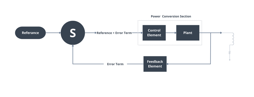
Figure 2 - Control System Block Diagram
In general, the 'Plant" of the control loop is dominated by the output capacitance of the power supply, creating a pole or a drop in gain and accumulation of phase delay as frequency increases. The purpose of the feedback element is to compensate for this drop in gain by adding gain over appropriate frequency ranges so as to assure that when overall loop gain reaches unity the possibility of positive feedback is avoided.
With inductive loads, the "Plant" is no longer just the output capacitor of the power supply; it is now compromised by an LC network. This LC network moves the pole to a lower frequency, and possibly to a region that does not have a phase margin to ensure stability.
This Loop Gain and Phase (Bode) plot in Figure 3 illustrates this phenomenon. Phase margin is the angle on the phase plot when the gain crosses zero. The ideal phase margin for a power supply is between 45˚ and 90˚, while below 45˚ the system is at risk of becoming unstable. The addition of the inductive load reduces the gain cross-over point from 1 kHz and 30Hz and the phase margin drops from 76˚ to 45˚. A system that was stable using a restive load now runs the risk of becoming unstable using inductive loads. Depending on system parameters, the new gain cross-over point that the inductance load generates may be even lower, or the phase plot may drop off quicker at lower frequencies.
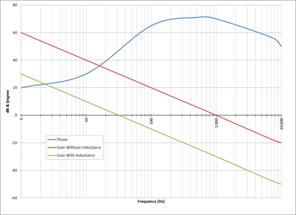
Figure 3 - Bode Plot With and Without Inductive Load
It's critical that the power supply selected to be designed with these criteria in mind, and that the topology and feedback methods allow for inductive loads. Otherwise, the network will need to be "tuned" specifically to the inductance of each load, which reduces the application options available to the system designer.
LiquaBlade: Astrodyne TDI's Water Cooled Power Supply
Astrodyne TDI presents a product offering sophisticated high-power equipment. This product is specifically designed to provide superior performance and key advantages in high DC power applications.
.png?width=700&name=Liquid%20Cooled%20Power%20Solutions%20(1200%20%C3%97%20627%20px).png)
LiquaBlade™ product line key features:
- 16.5 kW in a single 1U rackmount solution
- Programmable outputs: 0-500V
- Parallel series compatible for increased power needs
- Constant Voltage, Constant Current, and Constant Power control models
- Three-phase delta input (380-480VAC +/-10%)
- High-speed digital control
- .99 Power Factor (Active)
- Redundancy for 100% uptime
The LiquaBlade product line is a 1U, hot-swappable, 16. kW fully adjustable power supply, which can be operated from a 380-480VAC 3-phase input, and utilizes liquid cooling. The output can be programmed from 0-60V, 0-120V, 0-180V, and 0-500V. This versatility provides the LiquaBlade™ the ability to function in a wide array of applications. It utilizes a true power factor corrector front end, allowing for a 99% power factor, and less than 10% total harmonic distortion.
LiquaBlade™ boats an impressive power density of Up to 16.5kW power in a 1U high, 19” rack space and can function in harsh environments with coolant temperatures up to 50˚C. It is tolerant to AC line surges and sags per both IEC and SEMI standards. Regulatory agency compliance to UL60950-1 and EN61000-4, allows integration into a number of safety compliance systems, maximizing application flexibility while increasing overall solution safety for the end user.
The "drawer and shelf" configuration utilizes blind mate/hot-swappable quick disconnect electrical connectors and coolant fittings, allowing the fast exchange of power supplies in the event of a failure. Mean Time to Repair (MTTR) is kept at an all-time minimum while mitigating the need for special training field personnel.
Click here to learn more about our Liquid Cooled Power Supply Solutions.
LiquaBlade™ Water-Cooling Power Supply with Inductive Loads
LiquaBlade™ has been characterized with an 8mH dipole magnet used in semiconductor processing equipment for lon beam steering. As well as a 15mH dipole magnet used in proton therapy applications. Testing was performed to demonstrate closed-loop stability, and output the current command step response.
Figure 5 demonstrates the stability of the LiquaBlade in constant current mode while driving a 15mH dipole magnet. Note that the phase margin at the gain crossover point is 60˚, indicating excellent closed-loop stability. The phase angle at lower frequencies remains well above the 45˚ minimum required for stability. This suggests that with a large magnet with increased inductance, the gain crossover point will reduce, but the phase margin will always remain in a stable region.
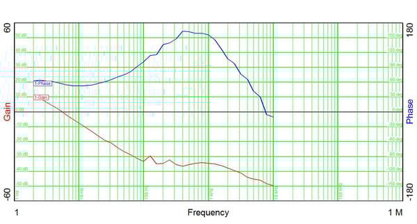
Figure 5 - 15mH Magnet Closed Loop Response
Yet another method to illustrate the closed loop stability is to perform an output current command step, and instrument the output current. A loop that is unstable will have sinusoidal oscillation of the output current, for one or more cycles. Figure 6 demonstrates a critically damped loop response with the output current quickly converging on its target without excessive oscillation.
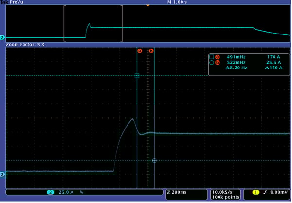
Figure 6 - 15mH Magnet Step Response
As mentioned earlier, along with closed-loop performance, operating point stability is also key to beam steering applications. Figure 7 is a stability demonstration performed on a LiquaBlade™ using a resistive load in constant current mode. Coolant temperature, load resistance, and line voltage were all modulated to record the effects (if any) on the output current's stability. This provides evidence that with a 10-degree change in coolant temperature the output current changed from 249.644Adc to 249.600Adc or a 44mAdc delta, (equivalent to 17.62PPM/˚C) of operating point stability. Likewise, stability as a function of output voltage shows evidence of 7.67PPM/Volt. There was no measurable change in output current as a function of input AC line voltage.
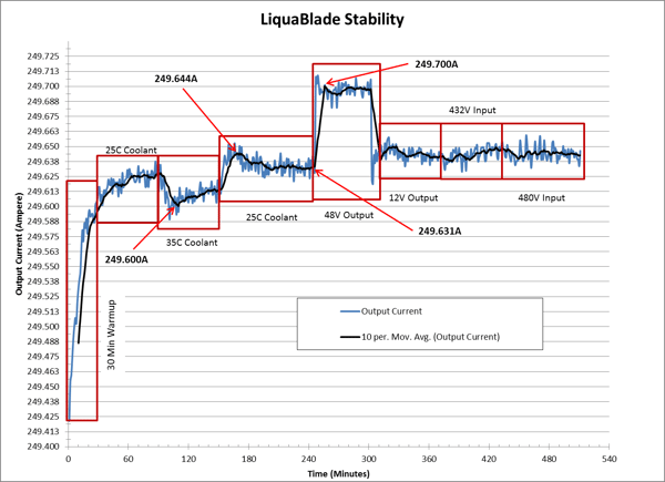
Figure 7 - Stability Plot
Power Supplies for Magnetic Inductive Loads
Power supplies utilized to drive magnetic inductive loads require a proper understanding and consideration of their unique needs. Closed loop stability, precision, and drift all need to be considered when selecting a power supply. The LiquaBlade product offers proven performance in all areas while offering a number of value-added features. Astrodyne TDI has leveraged its many years of experience designing sophisticated power products, to offer yet another product line well suited for your application.