RESOURCES
Introduction - General consideration for implementation of High Power DC include the following:
- Higher voltage yields lower current - Therefore power distribution and delivery should be kept at as high voltage as possible as to avoid the weight and cost of copper conductors.
- The Power Factor of the AC-DC power conversion process can have a significant effect on cabling and distribution transformer size (Harmonic currents often desired to be kept in compliance with IEEE-519.)
- Power conversion efficiency should be kept as high as possible to optimize reliability and reduce demand on cooling infrastructure.
Markets: Industrial, Medical, Information Technology, and Military.
Challenge: Available space has not increased, old designs have limitations.
Typical System Development - Background:
Three phase utility power is generally delivered to the facility at voltages above 10kV phase-to-phase (e.g 13.2kV). This is then transformed down to facility level power (typically 480VAC in North American, or 400VAC in other parts of the world) and used to power major systems such as heating, ventilation and air conditioning (HVAC) or lighting.
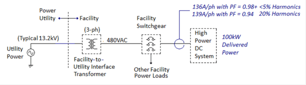
High power DC systems are normally operated from facility level power as to remove the need for an additional high power step down transformer.
Two scenarios for power converter electrical topologies are noted. One provides a power factor of 0.94 and produces THD >20% and measured current of 139A per phase. The other provides factor >0.98 and less than 5% harmonics, demonstrating it doesn't take a large swing in Power Factor to influence delivered THD.
Typical DC Systems:
Typical high power DC systems have utilized one of three approaches for AC-DC power conversion. All of these have a transformer operating at the utility line frequency. These methods are outline in the following three examples:
- Step-Down Transformer and Bridge Rectifier
- Thyristor Controlled Converter (SCR)
- High Frequency Switch Mode Post Regulator
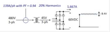
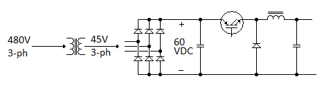
Example 1 - Step Down XFRM and Bridge Rectifier:
While being fairly simple, this approach is non-adjustable and has no means of regulating output power variations in input voltage. Also this approach results in a typical power factor of 0.94, with greater than 20% input current THD. Multi-phase transformers can be utilized to reduce THD, however, these come with the expense of a significantly more complex transformer and additional rectifier diodes.
Example 2 - Thyristor Controlled Converter (SCR):
Figure 4 illustrates the use of Thyristors, or Silicon Controlled Rectifiers (SCR's), to regulate output power. These devices allow control of output power to regulate delivered power against power line variations, as well as control the amount of power delivered to the load.
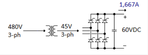
In figure 4, AC line voltage is stepped down via a transformer operating at the power line frequency. The rectifier bridge is realized via SCR's whose firing angle is controlled by an electronic circuit. By controlling the time at which the SCR's are turned on versus a given point on the AC waveform, output voltage can be controlled.
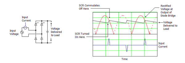
SCR Regulator Illustration
While this approach can deliver a wide range of adjustability with good regulation, it suffers from producing very high power line harmonic currents and waveform distortion. Input current THD of >50% is not uncommon. Also, these converters often suffer from regulation and ripple issues at low output power conditions.
Example 3 - High Frequency Switch Mode Post Regulator:
Output power can also be controlled via a post regulator operating off the output of the rectifier bridge, as illustrated in Figure 6.
High Frequency Switch Mode Post Regulator
This approach provides similar input harmonic performance as the unregulated supply of Figure 3. However, here output power is controlled via a high frequency switch mode converter, such as the Buck circuit shown in Figure 5. Operating at frequencies of 20-kHz, or higher, HFSM regulators provide wide range output power control and regulation along with high power conversion efficiency. These improvements come at the cost of increased complexity and cost, and this approach is still burdened with the size, weight, and cost of the line frequency transformer.
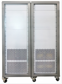
Traditional Cabinets:
Mechanical realization of traditional systems typically houses the transformer, rectifier and regulation circuits in a single cabinet. Figure 7 provides views of typical installations.
Further Limitations - Traditional Power Systems:
Monolithic, with non-modularized
- No ability to easily expand system power capability if load requirements increase.
- Likewise, if there is a failure within the power system, troubleshoot and repair will most likely require extensive do-construction by a skilled technician, resulting in a long mean time to repair (MTTR).
Large size -
- Typical utility line transformer has a volume of 180 liters (6.4 cubic feet) and weighs 500kg (1,100lb)
Forced air cooled-
- Even liquid-cooled heat plates still require air-flow through the cabinet for proper ventilation, resulting in the opportunity for the ingestion of dirt and debris which can ultimately compromise system reliability.
HSFM- Advantage: Power converter size can be reduced along with improved power conversion efficiency and low input current harmonics with in introduction of High Frequency Switch Mode (HFSM) technology.
HSFM Converter:
Figure 8 provides the power elements schematic for a typical HFSM converter operating from 480VAC, single phase power.
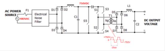
Figure 8 - HFSM Power Converter
AC Power is rectified to high voltage DC (750V) via an active power factor correction circuit, and then applied to a high frequency chopper circuit (operating at >=100kHz Switching Frequency). This provides >0.98 power factor and less than 5% input current THD. The full bridge chopper circuit presents a square wave to step down and isolation transformer T1. As this transformer operates at a frequency >1500 time the power line frequency, its size is less than 10% of the equivalent 50/60Hz part.
Secondary voltage of T1 is then rectified via diodes D5-D8, and then passed through low pass filter L1/C2. Delivered output voltage can then be controlled by controlling the switch on time duty factor of switches S1-S4. In order to operate reliably from 480VAC input power, semiconductor switches should be rated 1000V, or higher. Latest generation Silicon Carbide technology Mosfet transistors and Schottky diodes, rated to 1200V, provide unique opportunities for circuit optimization. Providing exceptionally fast switching speed, along with low conduction losses, these parts have enabled new levels of delivered converter performance and reliability.
Thermal Considerations - Limitations of Air Cooling:
A power system delivering 100kW of power at 90% conversion efficiency produces 11.1kW (38,000BTU's/hour) of heat. Removing this heat via moving air can present significant issues, including:
- Inability of moving air to handle heat loads being presented by modern equipment
- Moving air facilitates conductive debris infusion, compromising reliability
- Size of heat sinks, fans and equipment
- Power low of cabinet fans
- System-level airflow patterns are difficult to manage and maintain, resulting in a reduced reliability and system unavailability.
To address these, liquid cooling is often called upon for high power systems.
Temperature Rise:
The temperature rise of a given heated surface and the surrounding cooling media can be calculated as: DT = (hc x A) / Q
Where hc is the heat transfer coefficient (Watts per square meter x oC), A is the surface area (square meters) and Q is the amount of heat being transmitted (watts).
Benefits of Liquid Cooling:
Direct coupling of liquid to heat generating elements, as illustrated in Figure 10, eliminates inefficiencies and compromises moving air.
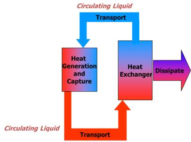
Figure 10 - Liquid Cooling Process
Benefits of Liquid Cooling are summarized, as follows:
- Increased Equipment Density
- Reduce Power Consumption
- No Audible Noise
- Dust and Debris Resistant
- Reduce Pollution (NO Bearing Wear, No Oil Evaporation, No Fluorocarbons)
- Increased Thermal Stability through Greater Thermal Mass
Liquid - Cooled Design:
- Coolant Type
- Flow Rate
- Operating Pressure
- Dew Point
Flow Rate needs to be matched to the amount of heat to be removed and allow temperature to rise. Likewise, pressure needs to be compatible with the materials used. Not enough pressure results in too little flow. Too much pressure results in ruptured elements. Condensation should also be considered if coolant temperature drops below the dew point of the surround ambient, which may result in condensation.
Astrodyne TDI Product Timeline:
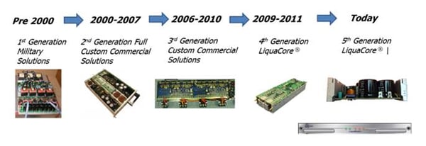
Evolution of Liquid-Cooled Power Systems in Astrodyne TDI
First generation, cold plate based systems led to highly integrated 2nd and 3rd generations systems which utilized 3D cooling plate shapes to capture heat from different shaped components. While these designs are very efficient from both the performance and cost aspects, they are not highly adaptable to different requirements. This led to the development of a scalable liquid - cooled technology first deployed in 4th generation product, which is referred to as LiquaCore. Utilizing a U shaped heat exchanger to present liquid - cooled surfaces to three sides of a printed wiring board assembly, LiquaCore provides high levels of both integration and flexibility. Fifth generation LiquaCore has taken the concept of integration and flexibility to the next level.
Fifth Generation Liquid Cooling:
As depicted in Figure 12, this patent-pending technology provides highly engineered, liquid-cooled aluminum rails on ether side of a printed wiring board assembly.
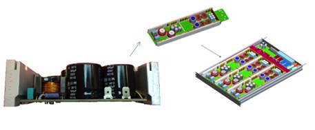
5th Generation LiquaCore Technology
The length of these rails can be adjusted, as necessary, for given application. This provides a mechanism for mounting power semiconductors in industry standard packages, with their junctions within 3mm of the liquid coolant.
Irregularly shaped components, such as toroidal inductors, have their heat conducted to the side walls via mounting brackets engaging both the component and the side wall.
LiquaCore assemblies can be connected in series through the use of interconnect technology derived from automotive air condition systems (ferrules and O rings).
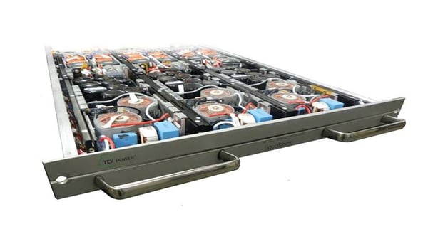
LiquaCore 16.5W Water-Cooled Power Supply:
Figure 13 represents an overview of Astrodyne TDI's LiquaBlade power converter which utilizes 5th generation LiquaCore technology.
LiquaBlade Power Module
LiquaBlade utilizes three LiquaCore assemblies operating in parallel contained within a 1U high mounting shelf. Six liquid-cooled rails are closely coupled to both the top and bottom covers of the assembly, providing effective thermal management of low power components not otherwise tied directly to the coolant. With the unit fully closed up, all internal components are fully protected from external air-borne conductive contaminants.
This modularized converter provides a 16.5kW per U on 19" Rack Space. Operating from 480VAC, 3-Phase Delta Input Power with Full Power Factor Correction, it leverages Silicon Carbide Mosfet Technology for high operating efficiency (>92%). Wide range output power control (from 0 to max) is user selectable between constant - voltage, constant - current, or constant - power via a serial digital control interface, making it an ideal choice for industrial process applications.
LiquaBlade converters are designed to be connected with their outputs in parallel or series to realize higher power systems.
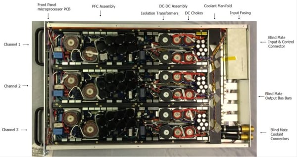
Figure 14 highlights the features enabling system implementation. System debug and troubleshooting can be conducted at the module level and blind-Mate Coolant and Electrical Connections enable very low MTTR. This feature also enable systems to be deployed with some module slots depopulated, allowing for planned output power expansion as host requirements increase.
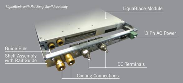
Figure 14 - LiquaBlade System Connection Features
Coolant manifolds, DC output Connections, control lines and AC input power connections are all organized to support a vertical routing plan. As seen in Figure 15, Power and services can easily be set for either top or bottom (or split) cabinet entry.
LiquaRack Power Systems are available with a power system controller to monitor and control both output power and the onboard cooling distribution system. Included are features such as leak detection and condensation prevention. The controller interfaces with the host systems though any number of protocols, including CAN bus, Ethernet, or Ethercat.
A summary of the systems advantages provided by LiquaBlade and LiquaRack is provided, as follows:
- Fully Power Factor Corrected for IEEE-519 Compliance
- Scalable and Blind Mate for low MTTR
- High Density - 16.5kW per U or Rack Space
- Wide Range Output Control - CV, CI, CP
- Full Digital Control Interface
- Outputs are Parallel and Series Compatible
- Liquid - Cooled - 55 degrees C coolant at 2gpm
- High Reliability in Aggressive Physical & Electrical Environments
Conclusion:
Latest generation liquid-cooled package designs, when coupled with highly efficient and reliable silicon carbide semiconductor technology, provide the system designer with new levels of system flexibility. Along with resistance to aggressive physical environmental conditions, provision of highly flexible controls make this technology ideally suited to demanding high power DC applications.