RESOURCES
Power supply specifications should be regarded as a central part of electronic product development. There is much to say about the best practices for developing products that need electrical power. Still, to avoid writing a book on the subject, today’s focus is on capturing and using the outcomes of those conversions that define a product.
Most customers we meet and work with consider that it is no longer sufficient to treat power provision within products or processes as an afterthought secondary to the item’s “big features.” Critical aspects central to the product’s operation will often be mirrored in the vital parameters of the power system’s mission.
This article addresses the underlying principles of outlining specifications for power supplies manufactured as a standard product. Such modular power systems must be carefully selected as they may be introduced late in the design cycle.
The approach proposed is not the only one that could be followed to achieve a good result. The one explained here will allow the reader to build a comprehensive specification and then find a system that meets the requirements “out of the box” or enables them to develop a unique product that meets the original needs.
Introduction to Selecting a Suitable Power Supply
Electrical engineers often get called upon to select rather than design a power supply from scratch. It might seem to the inexperienced designer that this task is deeply founded on spreadsheets of parameters of various products and many hours of investigation. This is a task that needs to be completed as soon as possible so that he/she can move on to other things. However, the knowledge one acquires during such an initial engagement is worth discussing in some detail rather than being left as an effort that gets forgotten or buried under new projects and timelines.
When searching and selecting a suitable power supply unit (PSU); there is a compelling need to specify a power solution as a sub-system that engages appropriately with other parts of a complete system. This suggests that there may be several shared interfaces with other components of the complete product, not just power connections.
Block diagrams are powerful tools that have been around since the 1950s. Prior to the introduction of the non-layer, the application was structured as a circuit with only one layer of hierarchy. However, with the increasing need to manage multiple interactions between various functions, it became necessary to identify specific functions from collections of components. Everybody who uses block diagrams appreciates the economical expression of inter-relationships between various functions within complex systems and follows the top-down approach to design. This ageless visual notion can be extended to help with product engineering, as explained in this article.
The process of selecting a suitable power supply against a specification involves acquiring figures for performance metrics and understanding what those metrics mean and how they relate to the application at hand. A datasheet for a power supply suited to a pulsed load application should have different parameters than one used for powering a frequency synthesizer used in a communications system (figure). On the first explanatory page of a datasheet, a manufacturer should indicate the appropriate parameters for the applications to which the PSU is intended.
Buy vs Make: Power Supplies
“Why not design a power supply from scratch?” you might say. The development of a high-performance power supply is now primarily in the hands of OEMs who specialize in manufacturing them. Products designed with line frequency-based power supplies can be bulky and heavy. The weight of power supplies is inversely proportional to the commutation or switching frequency. The contracting out of power supply development and production sees some exceptions to this 21st-century trend. With the advancement of power system technology, there is a stronger push towards the judicious use of limited resources to avoid duplicating complex efforts that may result in failures or regressions to obsolete technologies.
As a power supply manufacturer, Astrodyne TDI develops specialized power supplies that stand out from generic models. If you visit the company's website, you will find applications that involve semiconductor fabrication, industrial high-energy beam, and medical particle accelerators. There are synergies amongst different applications that Astrodyne TDI has noticed and incorporated in the generation of its product roadmaps to realize all kinds of power solutions that work between the alternating and DC domains.
Astrodyne TDI's engineers collaborate closely with their production teams based in various factories across the globe. As of now, they have manufacturing facilities in the United States and China. Moreover, Astrodyne TDI has recently finished setting up a new production unit in Penang, Malaysia.
Investing in new power switching technologies and developing specialized hardware and firmware is essential for companies like Astrodyne TDI. With their expertise, they can provide power solutions that meet challenging requirements within short timeframes, which may not be possible with in-house efforts. In addition to helping save time and resources, it is important to empower our customers to focus their engineering talent on critical aspects of the application, rather than being bogged down by peripheral activities. However, there is a condition that needs to be met - the dilemma here is that the supporting systems must still be well thought out and implemented, in addition to the main development effort. We circle back to the idea that the power system is an integral part of a product.
It is reasonable to consider developing a power system from scratch, provided that specific circumstances exist. It is indispensable for those who want to learn about the art of power supply design in a graduate move to other challenges or develop niche applications. At times, customers reach out to Astrodyne TDI seeking assistance.
The Origin of Power Supply Specification
In my experience, I have noticed that major capital projects typically start with a "business kick-off meeting." The director would have likely engaged in numerous discussions over several months or even years with their executives, senior engineers, subject matter experts from various disciplines, as well as marketing personnel, to explore the potential of a new product that could bring about fresh revenue streams.
During the business kickoff, we will include guided speculations on the returns on effort. Additionally, we will focus on a document that will be circulated beforehand, which will broadly outline how the product will work and the resources required to achieve the business goals. It will also describe the type of customer experience we are seeking with the product’s use.
The audience for the product implementation process will consist of a diverse team responsible for various aspects. This team will need to quickly sketch out parts of the design while also addressing any compromises that arise from combining existing work with new challenges.
After the power design engineering team reviews the business case, they will create a general outline of the project. As more details become available, they will create a preliminary block diagram. This diagram serves as a visual tool to help them investigate the project from multiple angles.
Firstly, quantify the primary power requirements of the loads by creating a power "tree".
Secondly, addressing the issue of distributing power to the various sinks that the electronic functions embody. Some of these sinks may demand strict controls on the noise levels on the power lines, while others may cope with higher noise levels. Additional interfaces may emerge from the block diagram, each requiring unique power supply decoupling at different points in the system. Power converters will often have some built-in filtering, and if they do not, then the question of how the effects of such noise get dealt with must be addressed.
Thirdly, the modules themselves may present unusual operating profiles e.g., a load that is pulsed in nature, or they might be highly inductive capacitive, or be nonlinear. It may be necessary to quantify specifications relating to the maximum amount of capacitance allowed as a load, as well as the rise time, pulse repetition and duty cycle, overshoot, and permitted settling time for a pulsed or stepped load.
A thorough inspection of the block diagram gives rise to applicable standards as well as specifications that can be mapped to critical portions of the product. We need to address how to deal with surges, transients, and over-voltages at any partition at the physical level where the application needs to connect to an external element. Now, we look for standards relevant to the application: Is this for automotive, medical, military or communication use? All these endeavors are supported by electrical standards, which must be acted on during the implementation of the power design to ensure conformance. It would be best to work gradually towards achieving safety and EMC compliance or certification. It involves a staged series of pre-compliance tests that are scheduled into the hardware’s development schedule. This allows the evolving system to be evaluated periodically to see if it meets certain requirements. Investments like this pay dividends in time saved in the qualification test house and reduced financial outlay.
Partitions act as boundaries that separate different modules from each other. Modules in this context are identified by the functions they perform which are unique to them. Viewing the block diagram in depth opens the prospect of applying standards correctly, a lesson akin to and as important as understanding what a parameter means in a specification. A well-designed block diagram, with properly aligned partitions, is invaluable to multidisciplinary teams during product design.
Internal partition will dictate specifications that are to be met for functional purposes. If we take the power tree as an example there will be minimum and maximum levels of DC power that need to be supplied as well as the speed at which the loads might be transitioning. At the point of load, there are output ripple, settling time and noise susceptibility targets to be set. When dealing with the edge partitions of a block diagram, it is necessary to adhere to the standards that apply to the specific type of power system. These standards vary depending on the type of system, such as those used in aircraft, automobiles, or operating theaters.
Your search for the ideal power system will be guided by general standards and the specifications the supply will need to meet.
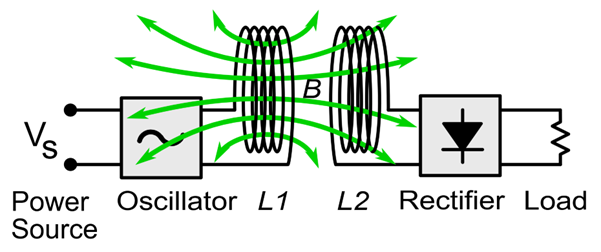
Figure 1 shows a block diagram for a wireless charging application.
There is an external partition between L1 and L2, inductors that form the power channel between the power source and load. The partition's arrangement follows SAE J2954 standards for Wireless Power Transfer for Light-Duty Plug-in/Electric Vehicles, including Alignment Methodology.
Economics of a Modular Power Supply Approach
When developing power supply units, Astrodyne TDI often starts with a standard product. The modular approach allows customers using products to build up a system from building blocks that are designed to work either independently of each other or as a raft of paralleled power units. Power outputs can be increased by connecting modules in parallel or series to achieve higher power or voltage capability than a single module can provide independently.
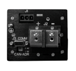
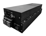
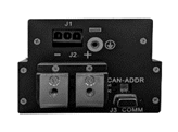
There are interfaces available that can work with multiple connected modules. Astrodyne TDI offers several different digital data interface standards, such as Ethercat and CANBus, which will allow commands and readbacks to and from the racked modules. Figure B shows an example of interfaces used, showing a liquid-cooled Kodiak power supply. The high-power assemblies are provided in kit form for onsite building and commissioning.
 |
 |
 |
(a)
 |
 |
 |
(b)
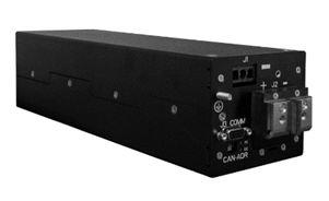
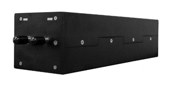
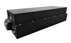
Figure 2 (a) shows the Kodiak 6 kW power supply, which is rated for 3-phase 480 V AC and includes DC power and data interface connections. (b) It also includes the CC Kodiak conduction-cooled 5.5 kW cousin.
One crucial interface for high-power applications is the 3-phase AC power utility. Optimal use of generating and transmission resources is the reason 3-phase is used. The utility can generate and distribute more power per unit of material used in the genthetor or transmission line. Depending on where our customers are situated on the globe, there will be different line amplitudes and frequencies and connection practices to contend with. Rectifying 3-phase AC electricity results in high voltage DC output with minimal voltage ripple compared to single phase. This evens out the high crest factors seen in currents drawn from DC links fed from single-phase AC. High power factors are critical for maximizing efficiency in 3-phase AC systems.
One way to handle the various sources of global 3-phase AC is to adopt the "universal AC path". This involves using techniques such as auto-ranging or modular switching to cover the entire range of 3-phase AC lines globally. This arrangement introduces more potential failure modes to the product, making it complex and costly due to the switching processes. Additionally, a system optimized for high-line AC may not be able to handle low-line AC current levels under constant high load. Then, there is an issue associated with the use of higher current-rated switching transistors and wider cross-section conductors than is necessary when the same module is operated in a high-line setting.
Astrodyne TDI has developed product solutions that simplify the complexities involved in supporting different utility requirements. Their products can support either single-phase 200-240V AC or 3-phase 400-480V AC utility requirements out-of-the-box. Additionally, their products have set options that allow users to choose the range of line voltages encountered within a particular country or territory. One of the Mercury Flex products has been adapted for medical power. Its AC front end accepts a 3-phase 400-480V AC input and converts it to a 400V DC link bus, which is used as a power feed for an array of Mercury Flex DC-DC modules that slot into the assembly. The Mercury Flex modules were designed to operate with a universal single-phase power supply of 90-264V AC. The Mercury Flex assemblies (which are dubbed “rectifiers”) are contained in the same chassis as the AC power distribution system. The Mercury Flex rectifiers were modified in such a way that they achieve compatibility with the 480VAC dictated physical spacings with respect to earth ground.
Another product developed by Astrodyne TDI is the 2.2 kW fan-cooled Hermes Flex. This is a universal single-phase 90-264V AC input-compatible PSU. Astrodyne TDI developed a 480V AC interface module adapted from a current AC front end. It has been engineered to seamlessly work with the original Hermes Flex, which operates as a DC/DC converter in this situation, requiring no changes to the Hermes Flex product, as shown in Figure 3.
Designing Block Diagrams that Feature “Natural Partitions”
We use this phrase to differentiate these elements from previous functional partitions. We have already talked about functional partitions which are those boundaries that come from consideration of a system block diagram. The physics of electrical power demand and supply goes beyond the product’s function into areas such as the atmospheric and ambient conditions. Each partition in the block diagram is examined from the viewpoint of the power dissipation that each individual module will produce.
.png?width=2240&height=900&name=HermesFlex%20Wide%20Range%20AC-DC%20Front%20End%20(1).png)
HermesFlex packaged AC-DC front end
-1.png?width=2240&height=900&name=HermesFlex%20(1)-1.png) HermesFlex
HermesFlex
.png?width=2240&height=450&name=480V%203-Phase%20AC%20compatible%20HermesFlex%20combo%20(2240%20x%20450%20px).png)
480V 3-phase AC compatible HermesFlex combo
Figure 3 shows the process of modifying Hermes Flex to work with a 3-phase AC input source, instead of a single-phase input.
There are certain environmental standards that are related to harsh environments caused by factors such as high altitude, atmospheric pressure, temperature, and humidity. These factors can make it difficult for heat to move away from the point where it is generated and dissipate into the surrounding environment or a heat sink.
Astrodyne TDI offers liquid-cooled solutions that are highly suitable for applications that require higher power levels, where investing in liquid cooling is cost-effective. This approach involves a coolant circuit that has a sealed design, which helps to maintain a well-regulated and controlled environment. The coolant circuit is supplied with cooled fluid from an external heat exchanger. Both the Kodiak and the Liquablade, as shown in Figure 4, are water-cooled. You can think of the coolant circuit in each of these power supplies as a highly integrated element of the PSU you get from Astrodyne TDI. Development work is nearing completion on a power module that is ideal for situations where neither fans nor coolants can flow through the PSU itself. The CC Kodiak, a conduction-cooled offering for 3-phase AC to DC conversion at the 6-kW level, is the cousin of the liquid-cooled version shown in figure 2. You will soon be able to see this new module in action. Mounting to the CC Kodiak on the top of a fluid-cooled cold plate makes for a very useful alternative.
Standards are available to address the potential interactions of the PSU with its surroundings, which can be represented by natural partitions. These standards cover a range of situations, such as marine or high altitude use where surroundings experience extremes of pressure, moisture, or corrosive environments. They also cover situations where surroundings are potentially explosive. Transients and surges in the mechanical world i.e. vibration and shock also become subjects of testing methods that are incorporated into the various available standards.
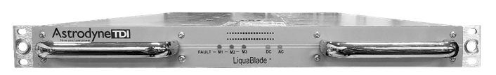
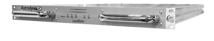
Figure 4 shows the Liquablade, which has a 16.5 kW output power rating and is liquid-cooled.
Summary
This article discusses the features of specifications that relate to partitions that are either internal or external to a system, which includes the power supplies that are a part of it. Additionally, the article describes several innovative solutions that Astrodyne TDI has implemented to make their products ideal for purchase and integration as a component of a complete product. This approach helps in saving time and money during the process of getting the product to market.
APPENDIX
A Glossary of Essential Power Supply Specifications
Besides the basic (minimum, nominal, and maximum) input-output voltage and current specifications seen in the datasheets, I have included some other power supply-centric specifications here – it is by no means an exhaustive list.
INPUT RELATED
- Input voltage range, whether it is DC or AC (single or 3-phase)
- Input line frequency range (for AC power sources)
- Delta or Wye configured (for AC 3-phase power sources)
- Required input capacitance
- Max sustainable peak inrush current
- Maximum input dV/dT, dI/DT (rates of change of input voltage, current)
- Input under-voltage lockout (UVLO)
- Input over-voltage lockout (OVLO)
- Maximum harmonic distortion generated by the power supply
- Crest factor
- Power factor and phase angle
- Peak-to-peak line ripple
- Power supply rejection ratio
- Compliant with EMC conducted emissions profile dictated by selected EMC CE standard
- Minimum restart time (this is generally associated with the time it takes for internal capacitors to discharge, fuses to reset, and thermistors to cool down) before re-energizing the power supply.
OUTPUT RELATED
- Output voltages and associated trim ranges.
- Maximum output voltage set point error
- Output overcurrent threshold.
- SOA settings – constant power, constant current
- Short circuit characteristic: Crow-bar, brick-wall
- Startup time
- Peak-to-peak output voltage ripple
- Output impedance
- Pulse repetition frequency
- Minimum rise and fall time
- Efficiency
FUNCTIONAL REQUIREMENTS
- If the power unit is to be programmable whether analog or digital interfacing is required
- Interface standard e.g. 0-24mA or CANBus, Ethernet for example
- Hot-swap capability
- Continuous operation through abnormal conditions (battle-ready)
- Protections: Over-current, over-temperature, short circuit shutdown
- Turn-on time, turn-off time
ISOLATION
- Digital interface isolation voltage
- Maximum working ratings for voltage between input-output, input to PE, and output to PE
ENVIRONMENTAL
- Maximum ambient temperature
- Maximum altitude
- Shock and vibration characteristics.
- Permitted Humidity
- Ingress protection