RESOURCES
Applications requiring pulsed currents with high slew rates are not well served with typical off-line AC-DC converters, where the usual approach for supporting these applications is to utilize a high bandwidth linear post-regulator after the off-line converter. This paper examines more efficient, reliable, and cost-effective alternatives to this approach utilizing high-frequency switch mode conversion techniques.
Introduction
Applications sometimes require pulsed electrical currents at high slew rates (i.e., the amount of time required for the current to transition from its minimum value to its maximum value high pulse repetition frequencies. Common examples are semiconductor lasers, as depicted in Figure 1, or pulse plating, as shown in Figure 2.
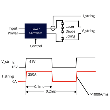

PRF: 5kHz
Peak Power: 10.25kW
RMS Power: 7.25kW
Average Power: 5.13kW
Figure 1 – Semiconductor Laser Application
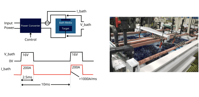
PRF: 100Hz
Peak Power: 32kW
RMS Power: 16kW
Average Power: 8kW
Figure 2 – Pulse Plating Application
As illustrated in both these applications, pulsed currents can require slew rates on the order of 1000A/ms, with currents in the hundreds of amps. Delivered current can be unipolar (as illustrated), or sometimes applications require bipolar pulsed currents.
Common considerations in these types of applications include:
- Significant power levels – 10’s of kW, or more.
- Processes can demand high delivered current slew rates
- Connection between power converter and load can present significant inductance which will tend to limit delivered di/dt.
- Offline power supplies generally have limited output slew rates.
Limitations of Off-Line AC-DC Converters Regarding High Slew Rates
Commercial AC-DC power supplies are designed for the primary task of providing a stable DC output voltage for constant or varying input voltages, or constant or varying output current loads. While they may support varying or pulsed output currents when operating with a constant output voltage, these supplies are typically not able to slew their output voltage quickly enough to force a pulsing current in the frequencies required by many applications. The main reason for this is the DC output filter capacitors.
In the case of high frequency switch mode (“HFSM”) supplies there are two criteria setting the value of these capacitors: First, is providing low impedance at the unit’s switching frequency to limit output ripple. Second is to provide adequate energy storage to limit output voltage excursions due to energy storage in the output filter inductor at both application and removal of load. Given these constraints, output capacitance is generally in the range of 30 to 50uF per ampere of delivered output current. For example, a unit rated to 60V at 100A (6kW) will typically have around 4,000uF of output capacitance.
Once the output capacitor is chosen, the unit’s output voltage or output current control loops must be adjusted to provide stable operation. For HFSM regulators the gain crossover bandwidth (“GCB”) must be below one half the unit’s switching frequency, but in practical terms GCB is normally well below 10kHz.
Output capacitors and the control loop’s GCB, along with the converter’s over-current protection (“OCP”) circuits limit the delivered slew rate. The OCP circuit limits the amount of charging current available to the capacitor in a program-up situation. For example, consider the above-mentioned unit. Let us assume the unit’s over-current protection circuit limits maximum current to 110% of rated = 110A. If output voltage is programmed from 25V to 50V with a resistive load which results in 100A at 50V, the output capacitor limits pulse current di/dt to 14.5A/ms.
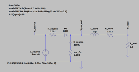
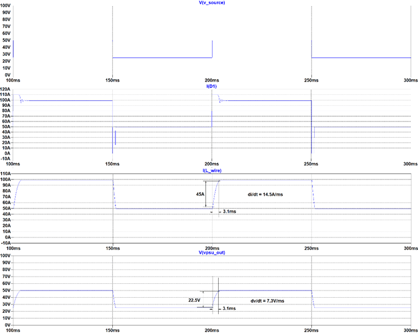
Figure 3 – Spice Simulation of AC-DC Power Supply Pulsed Output
The slew rate of the output voltage (7.3V/ms in the simulation) dominates the delivered current pulse slew rate. If we begin to decrease the output capacitor, we see the slew rate increasing, as illustrated in Figure 5.
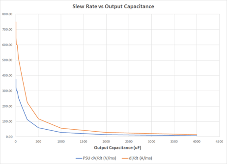
Figure 5 – Slew Rate versus Output Capacitor
As shown in Figure 5, output capacitance must decrease significantly before we begin to see an appreciable impact on slew rate.
Another method available to help improve slew rate is to temporarily increase output voltage during the current rise time. For example, with output capacitance of 125uF (1.3uF/amp), di/dt without any boost voltage is 409A/ms. If a 20V boost is added during the ramp up time, di/dt can be improved by 34% to 549A/ms, as illustrated in Figure 6.
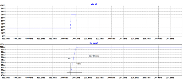
Figure 6 – Adding a Voltage Boost during Current Ramp-up
Conventional Means of Improving Delivered Slew Rates
As typical AC-DC power supplies cannot support ultra-high slew rates, a typical approach to solving the problem is to add a post regulator between the AC-DC power converter and the load, as shown in Figure 7.
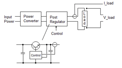
Figure 7 – Post Regulator
As depicted in Figure 7, this post regulator is often a transistor-based linear pass regulator. Voltage and current delivered to the load are monitored and transistor conduction is adjusted to optimize output current delivery. As indicated in the previous section of this paper, input voltage to the post regulator is usually maintained at a level above the required load sustaining voltage to aid in overcoming any load connection inductance during the current pulse rise time.
This topology places a heavy burden on the pass transistor as it must block the difference between the AC-DC PSU output and load voltage while also passing all the load current. Figure 8 illustrates this for a 1kHz pulsed 100A current delivered from a 60V source.
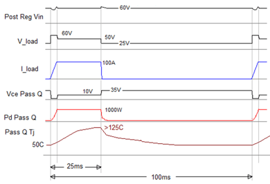
Figure 8 – Post Regulator Waveforms During Current Pulse
In the example shown in Figure 7, the pass transistor would likely be made up of multiple devices operating in parallel. Likewise, the control bandwidth of the post regulator will have to be high enough to respond quickly to changes in current demand as dictated by the control input.
Depending on design parameters, power in the pass transistor can cause issues with forward biased safe operating area, as well as repetitive thermal cycling effects impacting long term reliability. It is tempting to allow transistor junction temperature to reach near to its rated value during these excursions, but reliability theory teaches us this will have a detrimental effect on expected life of the part due to the repeated mechanical stress imparted to the die and package due to thermal expansion and contraction. When these parameters are taken into consideration very often the linear pass regulator becomes economical and volume burdensome to the end design.
Ideal Post Regulator Requirements:
Reviewing the parameters which the post-regulator must support, we find:
- Ability to support high pulse currents and high peak power
- Ability to support input overhead voltage to overcome lead inductance during pulse rise time.
- Control bandwidth high enough to support required pulse repetition frequency.
- Minimal output capacitance to support fast rise times (<5uF/A).
- Management of repetitive peak semiconductor power and junction temperature to assure long-term reliability.
Improved Post Regulator:
Given these considerations, Astrodyne TDI has developed post-regulator solutions based on high-frequency switch mode technology. Figure 9 provides the basic electrical schematic for a unit that supports up to 60V/30A output with input voltages up to 100V.
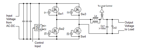
Figure 9 – High-Frequency Switch Mode Schematic
The circuit is built around a synchronous buck topology operating at a switching frequency around 200kHz at full load. The converter also features a hysteretic control topology which varies the switching frequency in response to output load changes. As depicted in Figure 10, hysteretic control will force Sw1 to be on (Sw2 off) continuously while output current is ramping up in response to a command. Hysteretic control provides optimal availability of input voltage to drive output current rise time.
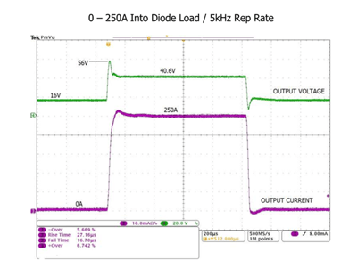
Figure 10 – Illustration of Hysteretic Control vs. PWM Control
An additional feature of the converter is the ability to reverse polarity on the delivered output. The four switches are modulated to set the output polarity as commanded by the external host system.
With an output capacitor less than 100uF (providing ~3uF/A at 30A) and high current control bandwidth, the circuit supports extremely high output slew rates. Converter blocks as depicted in Figure 9 can be connected in parallel to support higher output power. For example, when eight of these assemblies are connected in parallel, slew rates on the order of 8,000A/ms can be achieved in a semiconductor laser application, as depicted in Figure 11.

Figure 11 – Pulsed 250A Current with Multiple Converters
Power conversion operating efficiency is greater than 97%, with switch transistor dissipation less than 6W per part at full load. With conduction cooling to a heat sink, this allows for modest transistor temperature rise during pulsing operation, thereby limiting any impact on transistor life due to thermal cycling.
There are various possibilities for packaging the converters. For example, Figure 12 provides a monolithic implementation for a liquid-cooled, 80V input/output unit which supports output currents up to 250A.
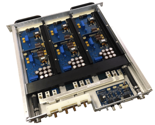
Figure 12 – High-Frequency Switch Mode Post Regulator
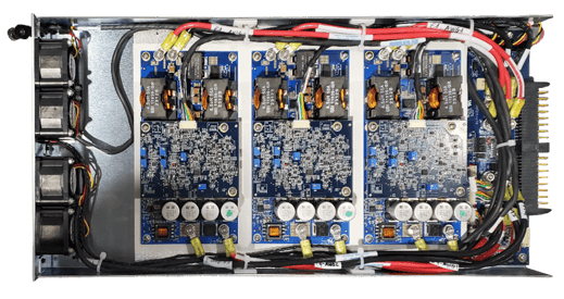
Likewise, a more modularized approach is possible. Figure 13 provides the concept for a 60V/30A assembly which can be paralleled with other like units to support currents to hundreds of amps.
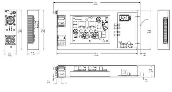
Figure 13 – Modularized Post Regulator
Power conversion efficiency is greater than 97% at full power, generating less than 50W of heat when delivering 55V at 30A.
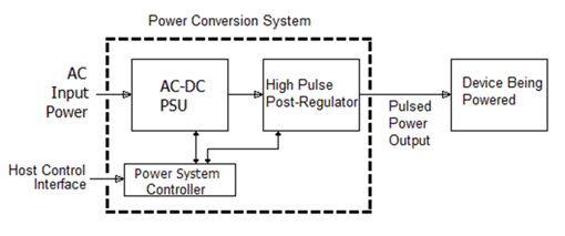
Figure 14 provides the top-level block diagram for an AC input system providing up to 15kW of pulsed power with output voltages up to 60V and output currents up to 250A.
15kW Liquid-Cooled High Slew Rate System
.png?width=500&height=188&name=Liquid%20Cooled%20Power%20Supplies%20(10).png)
Figure 14 – Complete AC Input Pulsed Output System
This system operates from 380-480VAC, 3-phase input, occupies 2U of 19” rack space, and features liquid-cooling. The control interface realized through Astrodyne TDI’s eLink2 Power System Controller can communicate with the host system through either a discrete analog or high-speed serial digital bus, such as Ethernet.
Other examples of the scalable nature of this technology are provided, as follows.
150A air-cooled post regulator module:
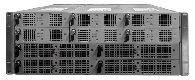
6kW Multi-Output Air-cooled High Slew Rate System
2.2kW Air-cooled High Slew Rate Power Module
Conclusion:
Utilizing optimized, high-frequency switch mode technology, an improved AC to pulsed DC output power system is provided. This system can provide output current slew rates greater than 1,000A/ms while also managing component reliability considerations resulting from thermal fatigue and safe operating conditions.