RESOURCES
DC/DC Power Converter Isolation
Electrical equipment is often well insulated from both earth ground and personnel. In such instances, Galvanic Isolation from utility power might not be required. Under such conditions, a simplified power converter topology can be employed, providing improved efficiency, power density, and cost.
A power source well suited for providing DC power to electrical loads such as Isolated DC/DC converters, electric heaters, magnet coils, battery chargers, or others is proposed. The output of this supply can be either fixed or variable, providing good versatility. The resultant power system is extremely efficient and compact if coupled with isolated, unregulated DC/DC converters. Likewise, excellent output dynamic range and control precision are available for loads requiring variable DC power.
Input harmonic currents are well controlled, providing far superior performance as compared to traditional thyristor phase-regulated topologies.
Generating AC-DC Power from a 3-Phase Power Source
This paper reviews power topologies for generating high-power DC from 3-phase power sources. A conventional liquid-cooled isolated 54V output is reviewed as a benchmark, and a novel direct, non-isolated, high-frequency switch mode circuit is compared at both the 54VDC and 380VDC bus levels.
The proposed topology has the advantage of maintaining its DC output relatively close to the earth's ground, minimizing the isolation required of connected equipment. This is in contrast with the conventional case, where the rectified output presents a voltage of similar magnitude as the input power line to appear from output to earth ground.
With the proposed topology, common-mode-induced noise on follow-on stages is significantly reduced, and conductor-to-earth insulation spacing also benefits from a corresponding reduction (with proper redundant protection built in for safety). In addition, while the voltage rating of power semiconductors needs to be 1200V on a bulk rectified 480 VAC line, the topology presented herein can be safely implemented, maintaining the same margins, as conventional 600V semiconductors.
The Need of High Power DC Sources
There is a common need in commercial, industrial, and military applications for high-power DC sources for heating, distributed DC power, battery charging, and other applications. At power levels above 50KW, 380-480 volt 3-phase power is the most common source chosen to control the amount of copper used in AC wiring.
Rectification of a 3-phase AC line results in a DC voltage with low ripple which does not require large amounts of capacitance to “fill in” the valleys typically found in single-phase systems. While a simple 6-diode bridge on the AC line has been around since rectifiers were first used, the resultant DC power has the same common mode component as the rectified AC line with respect to earth ground. It is, for this reason, the output circuit of a 3-phase rectified AC requires the same insulation spacing and treatment as the 3-phase AC line that feeds it. Figure 1 presents the conventional circuit implementation of a non-isolated rectifier topology.
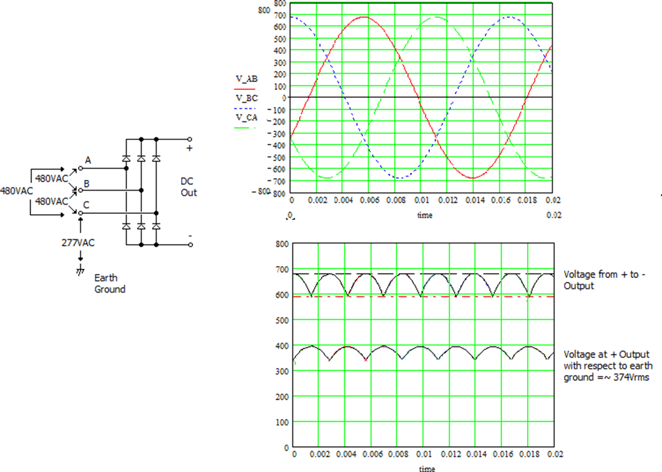
Figure 1 – Conventional Six-Step Rectifier and Resulting Waveforms
As depicted in Figure 1, assuming balanced voltages from each input phase with respect to earth ground, a 480VAC power line will exhibit a line-to-earth voltage of 277VAC. While the rectified output from the “plus” to “minus” terminals will provide approximately 650VDC, the voltage at the plus terminal or minus terminal with respect to earth ground will be approximately 374Vrms. Implementation of a circuit such as this one will require adequate insulation spacing and safety measures to accommodate this voltage.
DC Output Voltage Selection for an Intermediate Voltage Bus Feeding DC-DC Converters:
Most AC-DC power conversion systems for data processing systems employ a multi-stage conversion and step-down topology which includes an intermediate DC voltage bus. The choice of intermediate bus voltage depends on several factors. For systems intended to support downstream DC/DC converters, this includes the availability of appropriate DC/DC converters capable of converting DC bus voltage down to the electrically isolated low voltage typically required by the system. The two most common bus voltages are 54 volts and 380 volts. Each has its pros and cons.
The 54-volt bus has its origins over 100 years ago with the battery plants of early telephone systems. Over the years these systems have been refined, where power converters to feed the system have improved and ancillary system hardware has been designed. The main advantage of the 54V bus is that it is considered a “safe” voltage. In other words, it does not require high-voltage insulation.
However, this notion of safety stems from the lack of a shock hazard. It does not recognize the fact that a high current 54-volt bus can be quite dangerous unless properly insulated and protected. For example, a 124kW system requires a 2,300 amp/50V bus. At the 2,300-amp level, wires are not usually practical, and busbars are normally required. Often these busbars can be 3 or 4 inches wide, or wider, and they are usually spaced relatively close together. Anything conductive across the output bus will usually melt or even vaporize. Rings and watches are common items typically placed (accidentally) across a low voltage high current bus.
Power converters that generate the 54-volt power (generally referred to as “rectifiers”) have evolved over the years as power supply technology has progressed. Today, a typical rectifier is transformer isolated and operates from a 208-volt 3-phase line. Along with providing isolation from input to output, the transformer is required to convert high voltage/low current to low voltage/high current.
This current multiplication is an important aspect of the transformer-isolated design. A step-down converter with 54V output without the current multiplying/voltage reduction properties of a transformer generally requires up to four times the amount of high-frequency switching componentry as compared to a design featuring a transformer.
A 380-volt DC bus has its origins as the typical output of a switch mode power supply’s power factor correction circuit. Along with being supported by the mainstream power semiconductor part base, it is also a good choice to minimize copper. At the 124kW level, the total bus current is only 326 amps, which can be handled by conventional cables.
Breaking the load into 4 zones reduces the current in each zone to only 82 amps. Because of the higher voltage, insulation becomes essential, but flexible wire rated for 600V is commonly available and easy to work with. A summary of the advantages of each bus voltage, as derived from a 480V, 3-phase source, is shown in Table 1, below. Equivalent efficiency from a 230V-based system is also presented for reference.
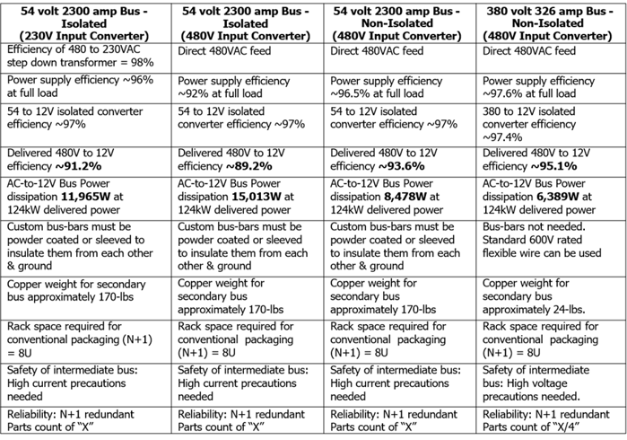
Table 1 – Comparison of Topologies for Low Voltage Output
Electrical Approach for Variable Output Non-Isolated Power Converters
Historically, electrical loads requiring variable power delivery have utilized Thyristor technology, or more lately Solid-State Relays, to modulate AC power prior to its delivery to the load. Figure 2 presents a simple realization of this approach.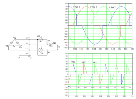
Figure 2 – Off-line Thyristor-based Regulator
In Figure 2, the SCR firing angle is adjusted to control the RMS voltage presented to the load. While this approach has the advantage of simplicity, it suffers from several issues:
- Input harmonic currents are very high (>50%)
- High peak input currents cause distortion on the input power line voltage which may affect other connected equipment.
- Delivered output voltage RMS value is difficult to accurately measure and control.
The proposed topology offers distinct advantages in these areas.
Electrical Approach for a Non-Isolated DC Power Supply:
The basis for a proposed, optimized non-isolated power supply is a three-phase rectifier followed by a DC/DC buck converter (which may be realized with multiple parallel converters operating out of phase). The topology results in an input power factor of 0.91 - 0.95 with input line harmonics of approximately 20%. A general view of the proposed circuit (with a single-phase DC-DC) is shown in Figure 3. The resistor Rx is shown as the measurement point for the resultant common mode voltage.
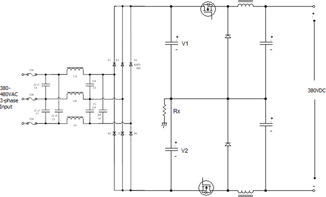
Figure 3 – High-Level Circuit View
The 3-phase AC input results in balanced AC line phase loading, regardless of channel loading or the number of channels used. A key feature of this topology is how it minimizes the common mode voltage to earth ground presented at the output, which affects insulation resistance requirements and potential ground fault currents in the load.
To maintain a relatively low common mode output voltage with respect to earth ground, the system is configured with a capacitive divider off the rectified DC bus. These capacitors provide low impedance at the switching frequency for ripple suppression. Their capacitance is low enough that they provide minimal energy storage at the power line frequency, eliminating the need for a separate inrush limiting circuit at the input.
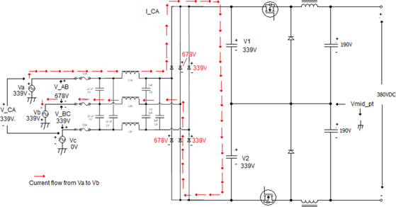
Figure 4 - Circuit Annotated for Analysis at peak of V_AB Voltage
Figure 4 presents the proposed circuit topology referenced to AC line voltages. AC -input voltage is modeled as three separate voltage generators connected to the earth-ground. The output in this example is a nominal 380VDC. Phase-to-ground voltages are set so this system could also be represented as a Delta Input connection with 480VAC from phase to phase. Figure 3 is annotated to show current flow and voltage distribution at the positive peak of the voltage from phase-A to phase B. A similar analysis could be done for other operating points.
As derived from Figure 3 and shown in Figure 4, the center point of the divider is near earth ground, with approximately 25% of the AC input phase voltage (14% of the line-line voltage) appearing at this node with respect to earth ground. With 480VAC input, the common mode voltage with respect to ground will be 97 volts peak (56VAC RMS) at 3 times the line frequency.
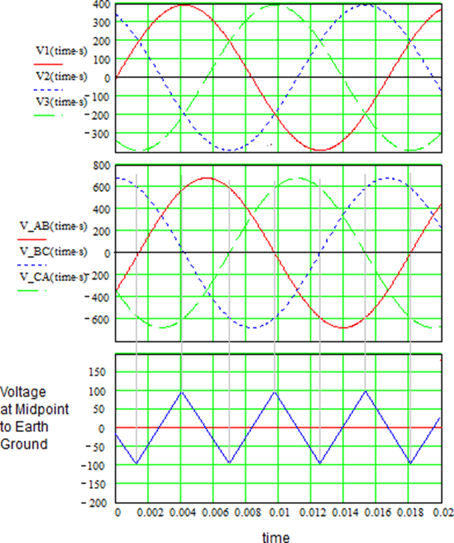
Figure 5 – Input Line Voltages and Voltage at Center Point
The following circuit description refers to the schematic of Figure 5, which can be one of three independently controlled channels in a single 1U rack mount assembly. For this example, each channel is sized to provide 5.4 kW (54V @100A or 380V @ 14.2A). The 3-phase AC input first passes through an EMI filter which reduces high-frequency emissions. Inductor L1 is a three-winding common mode choke, and C1-C3 and C4-C6 form a PI filter.
.png?width=614&height=440&name=Basic%20Power%20Circuit%20Schematic%20(54V%205.4kW).png)
Figure 5 – Basic Power Circuit Schematic (54V 5.4kW)
Diodes D1 through D6 rectify the 3-phase AC power producing a DC bus that is nominally 680VDC with 480VAC input. This configuration results in a very low DC ripple on the 680-volt DC bus.
This DC bus then feeds multiple DC buck converters (4 in this example). Each converter is driven from one phase of a clock, staggered 90 degrees apart in the 4-phase case. The drive points are labeled to coincide with their relative phase angles (0°, 90°, 180°, and 270°) with the high and low side drives for each phase shown. The high and low side drive signals are identical for each phase, being supplied by separate windings of an individual drive transformer for each phase. In the case of the multiphase topology, both input and output ripple tend to cancel.
There are several options for controlling the buck converters. One method would use a special purpose 4-phase DC/DC controller IC such as the HIP6303. This has the advantage of being an integrated controller for all four phases. However, it would need to be adapted to the required output voltage, and current sensing is via R-ds(on) monitoring. Using a microcontroller would enable the 4 phases to be well controlled and the details of current and voltage feedback could be adapted to the system’s needs. A more conventional method would be to simply use four PWM controllers (such as a UC3844) synchronized to a 4-phase clock.
To maintain a relatively low common mode output voltage with respect to earth ground, each buck converter is configured with a capacitive divider off the rectified DC bus. The center point of the dividers formed by C7/C8, C11/C12, C15/C16, and C19/C20 forms a phantom ground point. Each channel has a positive and a negative buck converter with respect to this point, controlled with the identical PWM gate drive signal.
Consequently, the resulting DC output is centered on the phantom ground point, which is always within 100 volts peak of earth ground. In addition, the fact that the drive signals are always identical means that the positive and negative halves will always remain balanced, within the tolerances of the inductors and capacitors. Any externally induced imbalance would result in a higher current on the higher voltage side, bringing the converter back into balance without the need for additional balancing circuitry.
When Q1 and Q2 close, current flows from the input DC bus through inductors L2 and L3, delivering current to output capacitors C9 and C10 and the load. When Q1 and Q2 open, diodes D7 and D8 are forward-biased by inductors L2 and L3, and currently continue to flow to the output. The Ripple current in the inductors is approximately 5A P-P at full load or less in the case of the 380V version. The duty cycle of the drive signal is controlled to produce the required DC output while remaining synchronized to the other 3 buck converters. An overvoltage crowbar circuit protects the output in the event of a buck switch failure.
Using a buck topology rather than a boost topology means that an AC input surge or swell will not get passed on to the output. With the series switches and output chokes, all transients are limited in their rate of rising by the value of the output choke, and the control loop has time to detect higher voltage on the output and end that particular switching cycle. With a conventional boost, PFC operating from a 208 or 240-volt line, any voltage greater than 269 VAC will cause the peak of the AC sine wave to “poke through” the 380VDC output and get passed on to the following stages. This is inherent in the boost topology.
Ripple currents from the DC/DC converters tend to cancel each other, allowing the use of a relatively small amount of output bulk capacitors. An added benefit of less output capacitance is faster output programming speeds and transient response. Using a high-speed digital interface, such as PMBus or Ethercat, the system will be able to accept and execute voltage set commands with high precision and at a 1-mS rate.
Figure 6 shows a high-voltage implementation of this buck converter. By raising the bus voltage to 380V, the current drops from 100A down to 14 amps. At this current level, a single-phase buck converter is more than adequate. However, the smaller voltage difference between the input DC bus and the output voltage at the low line (509VDC to 380VDC) means that significantly more capacitance is required if a 20mS holdup time is required. A 54-volt bus only requires 8 capacitors (470uF nominal each) while the 380V output requires 18 of the same capacitors to achieve the same 20mS holdup time. However, even with an additional 10 electrolytic capacitors, the 380V version is still approximately 5 inches shorter than the 54V version.
.png?width=624&height=457&name=Basic%20Power%20Circuit%20Schematic%20(380V%205.4kW).png)
Figure 6 – Basic Power Circuit Schematic (380V 5.4kW)
Oftentimes in industrial applications, higher power levels are required. The converter depicted in Figure 5 can be adjusted for higher voltage output, providing significantly higher power at up to 400VDC output. In this example, 60kW is easily achievable from an assembly.
Product Comparison LIQUABLADE™ Liquid-Cooled Power (16.5KW Isolated Example vs 60KW Non-Isolated)
LiquaBladeTM Liquid-cooled AC-DC Power Supply LiquaBladeTM Non-Isolated Power Supply (60kW)
| LiquaBlade™ Liquid-Cooled AC-DC Power Supply | LiquaBlade™ Non-Isolated Power Supply (60kW) |
.png?width=361&height=240&name=Fourth%20Generation%20Air-Cooled%20Design%20-%20%20Mercury%20%26%20HermesFlex%20(4).png)
|
.png?width=373&height=248&name=Fourth%20Generation%20Air-Cooled%20Design%20-%20%20Mercury%20%26%20HermesFlex%20(5).png)
|
| LiquaBladeTM | Isolated 1U | Non-Isolated 1U |
| Power | 16.5KW | 60KW |
| Mechanical size | 1U | 1U |
| Power/module | 5.5KW | 20KW |
| AC Input | 380-480VAC | 380-480VAC |
| Power Factor> | 0.99 | 0.9 |
| Output voltage | 10-500V | 10-480VDC |
| Modular/scalable | Yes | Yes |
| Efficiency | 91% | 98% |
| Water Cooled | 1.5GPM @ <10psi | 1.5GPM @ <10psi |
| Converter Size: | 1.75” x 17.5” x 31.2” (44 x 444.5 x 793mm) |
1.75” x 17.5” x 31.2” (44 x 444.5 x 793mm) |
Table 2 – Comparison of isolated vs non-isolated LiquaBlade™
As detailed in Table 2, when galvanic isolation is not required at the load, a non-isolated design offers significant advantages in size, efficiency, and cost.
Isolated vs Non-Isolated Power Converters
The choice between isolated and non-isolated converters depends on many considerations. Safety may dictate the requirement of the application for isolation, while others may just benefit from a floating output to reduce ground loops or shifting of reference voltages. Nevertheless, when isolation is not required, a non-isolated converter may provide a decrease in cost, size, and an increase in efficiency. Understanding the costs and benefits of isolation is important in choosing the right converter for an optimized design.
In some applications such as resistive loads, LED drivers,s or in cases where you have a second converter with isolation. Non-Isolated is most likely a recommended solution.