RESOURCES
Overcoming Power Converter Challenges with Water Cooling
Power converters present unique challenges in electronic packaging and heat management. Their concentration of electrical energy, propensity for electromagnetic interference generation, integration of heavy, irregularly shaped magnetic components, and requirements for uncompromised reliability and affordable cost requires careful consideration. This paper outlines these challenges and traces the evolution of packaging techniques utilizing liquid cooling to address them. This evolution has led to the latest generation designs that achieve unsurpassed levels of thermal management, packaging density, and product reliability.
Download PDF Version
Consideration for Water-Cooled Power Supplies
Historically, most power conversion solutions have utilized either natural or forced convection cooling. However, specific application situations, such as high-power levels or the need for protection from environmental contaminants, may dictate conduction cooling to a liquid-cooled heat dissipation element as the preferred solution.
Several basic questions need to be addressed when considering packaging and component options for a liquid-cooled power conversion solution. These include the electrical topology to be employed; power converter modularity and incremental converter size and power rating; physical environment size constraints; temperature rating of components; ease of manufacturing and repeatability for quality and system cost control.
Each of these will be considered in the following sections of this paper, along with a review of the historical approaches to address them. Finally, the latest generation liquid-cooling packaging techniques will be discussed, pointing out how design evolution has produced new levels of performance and economy.
Thermal Conductivity of Water-Cooled Power Supplies
Liquid, such as water, provides the ability to transfer heat very effectively. Table 1 shows the differences in thermal conductivity between water, copper, and air.
| Compound | Specific Heat (kJ/kg °C) |
Density (g/cm3) |
Conductivity (W/m°C) |
| Air (STP) | 1 | 0.00 | 0.017 |
| Copper | 0.37 | 9.17 | 391.1 |
| Water | 4.18 | 0.99 | 0.59 |
As noted in Table 1, water has 4.18 times the heat capacity of air and its density is 1000 times greater than that of air. Putting these together, the heat capacity of water for a given volume is 4,180 times greater than that of air. Thus, water provides a much more effective means of transferring heat. Translating this into physical terms, for a given amount of heat an air-cooled solution will require a vastly larger surface area available to transfer this heat. Liquid cooling often becomes attractive when there is a need to handle heat without utilizing excessive space.
Liquid cooling does not come without its issues. Among these are safety (due to the co-presence of liquid and electricity) and cost (due to plumbing, cooling circulation systems, and heat exchanger cost). However, as industrial process requirements, data processing, communication networks, and military systems continue to require ever-increasing power, there is a compelling need to have cost-effective, reliable liquid-cooled power conversion systems.
Electrical Topology Considerations for Power Supplies
As depicted in Figure 1, the typical paradigm for realizing high-power AC-DC systems is to utilize large components to handle the current and energy densities presented. While constructing the converter around high-power conversion building blocks may seem logical from the viewpoint of minimizing component count, it presents the system with several compromises.
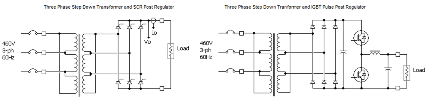
Figure 1 – Typical High Power DC System Realization
Due to inter-wiring inductance and circuit capacitance considerations, large physical component size generally limits the converter’s operating switching frequency. This in turn limits system control bandwidth and can compromise operational considerations (speed, precision, accuracy, etc.). These effects become even more pronounced if the converter utilizes silicon-controlled rectifiers operating at the incoming power line frequency.
Large converter building blocks also present challenges to system scalability, limiting the ability to optimize the power converter size for a given system deployment. In addition, providing redundant channels to assure no loss of performance if one of these building blocks suffers a failure is often not economically feasible. Likewise, the ability to modularize these building blocks to simplify repair and maintenance is also compromised.
Given these considerations, Astrodyne TDI has advocated a building block approach that facilitates the use of printed wiring boards to carry the required currents (for repeatability), utilizes packages and components commonly found in the mainstream power supply market (for availability and cost), and allow operation at switching frequencies up to 200kHz or more (to reduce size). Core converter circuits producing power on the order of 5-6kW meet these general requirements. Figure 2 illustrates this principle, where 5.5kW single-phase input building blocks are configured in groups of three to support a high-power requirement.
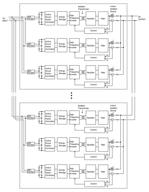 Figure 2 – High Power System with 5.5kW Power Converter Building Blocks
Modular AC-DC Power Converter Considerations
Perhaps the most obvious tradeoff in connecting multiple 5-6kW converter building blocks in parallel to support high power systems is the greater number of components required. However, as mentioned earlier these components will enable definite system benefits, including active power factor correction, increased control bandwidth for better system speed and accuracy, the affordable realization of the N+1 redundancy model, and the ability to properly scale the power conversion solution to the size and economic constraints of the system.
When effective design and manufacturing practices are employed, modern high-frequency switch mode converters can realize extremely high Mean-Time-Between-Failure (MTBF) levels. Practices included in realizing these reliability levels are detailed in Astrodyne TDI white paper TW0059 – Power Conversion Reliability.
As an example, consider a system that delivers 44kW, made up of nine 5.5kW converters which provide 8+1 redundancy. If each of these core power circuits delivers an MTBF of 500,000 hours and the failure of an individual block does not compromise system availability, then the MTBF of the system (measured as the mean time between events where the system cannot support its required output power) is greater than 100,000 hours.
Quite often, converters with large, monolithic conversion blocks end up utilizing components close to their rated limits of current, voltage, and temperature. This can result in compromised MTBF, at or below the values demonstrated in the above example for the moderate power block case.
When looked at from this perspective, Astrodyne TDI believes the tradeoff between a number of components and perceived system complexity leans heavily in the direction of lower power conversion building blocks and modularity. This practice has been successfully employed by high-power telecommunication and networking DC power systems for many years.
AC-DC Power Converter: Physical Environment Considerations
Space available for power conversion equipment is almost always a system constraint and realizing power conversion in a reduced volume is generally looked at as an advantage. Most high-power industrial systems in the market today, especially if they require galvanic isolation between utility power and the end application, rely on online frequency transformers. These are large, heavy, and expensive (especially in terms of their copper use).
High-frequency switch mode power conversion building blocks provide the advantage of drastically reducing the size and volume of the isolating transformer element. Along with this the previously mentioned benefits of active power factor correction, increased operational bandwidth and redundancy can be realized. Compared with line frequency transformer-based systems, the high-frequency switch mode typically provides volume savings on the order of greater than 300%, with weight savings of up to 70%.
Modularized, moderate-power converter building blocks also offer the opportunity to ease system maintenance and repair. If something goes wrong in a large, monolithic converter, it generally requires a skilled technician and many hours of downtime to troubleshoot and repair the system. On the other hand, a modularized system can be maintained by less skilled personnel in a fraction of the time. Figure 3 provides a photo of such a system.
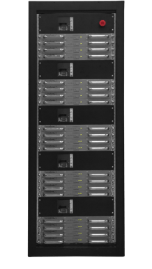
Figure 3 – AC-DC Power System utilizing 16.5kW 1U High Modules
Maintenance of the system shown in Figure 3 entails identifying a defective module and then removing and replacing it. Modules can be made available with a blind-mate feature that further simplifies this process.
Thermal Management for Liquid Cooled Power Supplies
Key to the reliability of any design is the proper management of component temperatures. When designers consider liquid cooling, the first thought that comes to their minds is “let’s get a cold plate and start bolting components to it”. While it seems straightforward, this approach leads to many compromises. As shown in Figure 3 under “1st Generation Military Systems”, Design for Manufacturing (“DFM”) suffers as this approach requires significant amounts of skilled manual assembly. In addition, the cost of the liquid-cooled cold plate is often found to be excessive.
Figure 4 – Evolution of ATDI Liquid Cooled Designs
Perhaps the most significant compromise with 1st generation designs is, while they can be effective at capturing heat from major dissipating components, significant amounts of heat may not be well coupled to the cold plate. This results in excessive internal air temperatures within a chassis enclosure. Even with coolant temperatures on the order of 35oC, this can easily result in internal chassis temperatures exceeding 95oC, to a point where low power passive component reliability is compromised.
As liquid-cooled designs evolved, they gravitated toward highly customized, extruded aluminum cold plate shapes that are more economical than copper tube/aluminum plate designs and provide effective cooling for both regularly shaped components (such as power semiconductors), and irregularly shaped components (such as magnetic parts). Moreover, these designs provided an opportunity to control internal air temperatures by providing an effective cooling path to chassis side walls, providing a convection path for internal components that are not directly connected to the cold plate.
As demonstrated in Figure 4: 2nd and 3rd generation examples, these designs were successful in terms of thermal management and providing effective product solutions for specific applications but being so specific they proved difficult to migrate to other applications. This ultimately led to the strategy shown as 4th generation, or what was branded as Astrodyne TDI “LiquaCore®”.
LiquaCore® was conceived as a modularized, scalable solution for liquid-cooled applications. As shown in Figure 5, it developed a standard extruded cold plate in the shape of a U, into which a power conversion PCB assembly can be placed.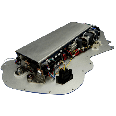
Figure 5 – Fourth Generation Liquid-Cooled Design - " LiquaCore®”
Surrounding the electronic components with a liquid-cooled aluminum structure, LiquaCore® provides adequate cooling for the power conversion building block. Power semiconductors are mounted to the side walls via thermally conductive insulators so that semiconductor junctions end up approximately 2-3mm from the coolant, providing very effective thermal transfer. Irregularly shaped magnetic components were contained in a separate aluminum structure that is filled with a thermally conductive potting compound.
Further design evolution on original LiquaCore® designs resulted in 2nd Generation LiquaCore®, as shown in Figure 6.
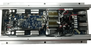 Figure 6 – Second Generation LiquaCore®
The U-shaped extrusion has now been designed to accept PCB assemblies as drop-in elements, while transformer cooling now features a cast structure that allows for thermally conductive potting of these irregularly shaped elements. Coolant passes through the side walls of the extrusion, with a turn-around executed at one end of the chassis through an additional bolted wall (not shown).
The latest evolution of LiquaCore® is Astrodyne TDI’s LiquaBlade™ design pictured in Figure 7. LiquaBlade™ features extruded side walls that carry the coolant from and to distribution manifolds. These provide effective cooling for power semiconductors, which are mounted to these side walls via insulating boots and spring clips.
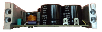
Figure 7 – LiquaBladeTM Power Converter Assembly End View
Figure 8 provides a plan view of a 1U high LiquaBlade™ power module assembly. (Please refer to the document LiquaBlade™ Theory of Operation for a detailed description of unit electrical operation.) This module provides three power conversion channels, each rated at an output power of 5.5kW for a total module power of 16.5kW.
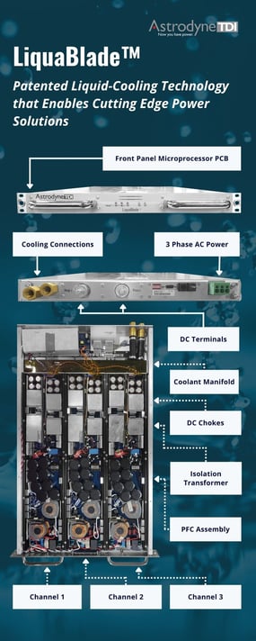 Figure 8 – LiquaBlade™ 1U High Power Module
Each PCB assembly features its own set of LiquaBlade™ cooling rails. These rails are connected to distribution manifolds, and in series with each other, via ferrules and O rings. This technology, adapted from automotive air conditioning systems, provides robust, leak-resistant connections which have been pressure tested to over 200psi. Each module produced undergoes extensive coolant containment testing, including pressurized leak testing and coolant temperature cycling, assuring reliable, leak-free operation when fielded.
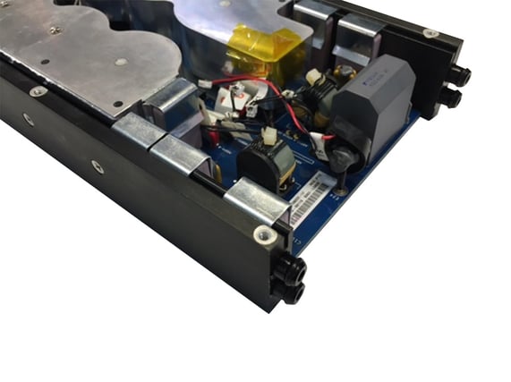 Figure 9 – LiquaBlade™ Cooling Rails and Connection Ferrules
Magnetic components are coupled to the side rails via cast aluminum structures into which they are potted with a highly thermally conductive compound that is also mechanically compliant. The entire blade pictured in Figure 8 features blind mate electrical and coolant connections such that it can be slid in and out of a system to support a low Mean Time to Repair (MTTR) for system maintenance. Figure 10 provides a view of these blind mate connections and the mounting shelf designed to accommodate them.
System-Level Considerations for Liquid Cooled Power Supplies
Liquid-cooled solutions also need to be reviewed as to what happens if there is a leak or condensation. As mentioned earlier, LiquaBlade™ power supplies are carefully designed and manufactured to prevent coolant leaks. However, as with any system parameter, the possibility of leaks should be considered. The best way to protect against coolant leakage either inside or outside the LiquaBlade™ module is to monitor the system for liquid accumulation toward the bottom of the system. If the liquid is detected then coolant flow to the system should be terminated, and input power removed from the system.
Likewise, condensation due to humid air coming in contact with cool components is another area of concern. When selecting coolant temperature, it is important to take into consideration the Ambient Air Dew Point to prevent condensation, ensuring the temperature of the coolant is sufficiently higher than the ambient air dew point. All PC board assemblies within LiquaBlade™ are conformally coated to help prevent insulation compromise due to small to moderate amounts of condensing humidity. However, if the power system is to be operated in areas where condensing humidity is a genuine concern, a power system controller that monitors humidity and coolant temperature is available. This will limit coolant flow to the LiquaBlade™ modules while they warm up so as to prevent the possibility of condensation.
Astrodyne TDI’s LiquaCore® and LiquaBlade™ Designs
Learning achieved from years of experience has resulted in Astrodyne TDI’s LiquaCore® and LiquaBlade™ designs. These provide exceptional levels of thermal management, design flexibility, maintainability, and cost-effectiveness. LiquaBlade™ opens the opportunity to leverage high-frequency switch mode conversion in high-power DC systems that traditionally have been the exclusive domain of line frequency-based solutions, providing significant benefits in terms of size, flexibility, performance, and system availability.