RESOURCES
Electrical systems carrying currents from 50A to 6,000A require current transformers (CTs) that accurately measure load and respond to fault conditions. Utility equipment, motor control centers, switchgear and panel boards depend on precise current sensing for protection and metering. Mismatched specifications introduce measurement errors and may cause thermal failures or equipment damage.
Engineers must evaluate type, construction, ratio, accuracy class, burden capacity and insulation rating. Each factor affects performance under continuous load and fault conditions.
Table of Contents
- What Are the Primary Types of Current Transformers?
- Construction Types for High-Current CT Applications
- Technical Specifications for Selecting a High-Current CT
- Why Insulation Class Matters for Reliability
- Matching CT Construction to Your High-Current Application
What Are the Primary Types of Current Transformers?
Electrical engineers choose from three functional categories based on application requirements:
- Protection designs address circuit abnormalities.
- Measurement designs prioritize billing-grade accuracy.
- Dual-purpose units combine both capabilities in a single assembly.
Design priorities differ across categories. Protection circuits require high saturation thresholds to maintain signal integrity during fault surges. Metering circuits require stable accuracy across normal operating ranges. These differences mean that the right current transformers for utility equipment may differ from those in industrial applications.
Protection CTs
Fault detection drives the design of protection-grade CTs. Circuit breakers and switchgear require relay signals that remain accurate during short-circuit events. Units with 6.5-inch and 7.5-inch windows accommodate primary conductors from 50A to 6,000A and deliver standardized 5A secondary output.
High instantaneous currents occur during ground faults and phase-to-phase shorts. Core materials and winding designs resist early saturation, preserving waveform fidelity during transient events. Protection-grade units maintain signal quality long enough for protective devices to isolate faulted sections before thermal or mechanical damage occurs.
Measuring CTs
Revenue metering and energy management systems require stable, accurate current measurement. Metering or measuring transformers deliver the necessary precision within specified burden and current ranges. Panel boards and distribution equipment use measuring units that feed load data to billing systems or consumption-tracking systems.
Accuracy takes precedence over fault handling in metering applications. Engineers specify tight tolerance classes to meet utility standards and regulatory compliance. Billing-grade performance ensures revenue calculations reflect actual consumption.
Dual-Purpose CTs
Space constraints and budget considerations drive the adoption of dual-function designs. A single unit provides metering accuracy under normal conditions and adequate relay performance during faults, reducing both installation footprint and wiring complexity.
Modern panel assemblies benefit from integrated functionality where enclosure space is limited. Dual-purpose units balance steady-state accuracy with transient saturation capability without installing separate devices.
Construction Types for High-Current CT Applications
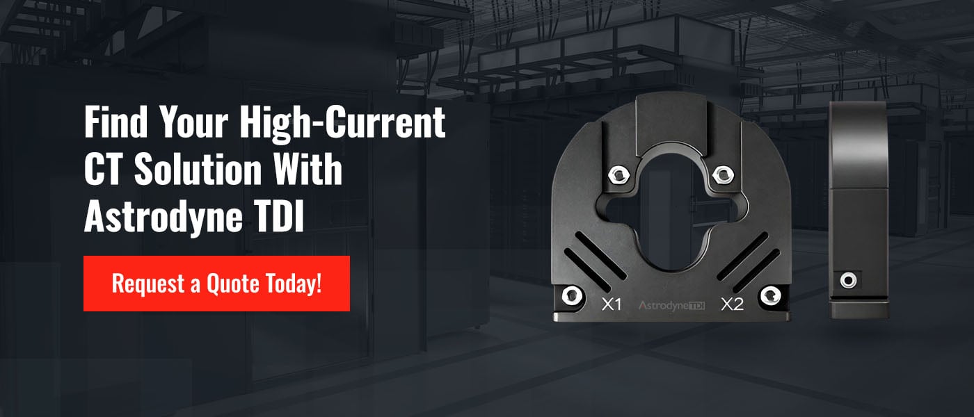
Physical configuration determines the installation method, conductor compatibility and environmental suitability. New construction allows any configuration. Retrofit work often requires split-core designs to avoid circuit de-energization. Current transformer products for high-current applications come in multiple physical configurations to address installation constraints.
Bar Type, Window Type, and Split-Core
In bar-type construction, the primary conductor is integrated directly into the assembly during initial manufacturing. Window-type construction involves passing conductors through an aperture. Alternatively, split-core construction uses hinged or bolted halves that separate to encircle existing busbars.
Window-type designs are commonly used in panel boards and switchgear installations where conductor routing differs. Split-core units are preferred for retrofit projects because they allow field technicians to install transformers without de-energizing circuits, saving both time and money.
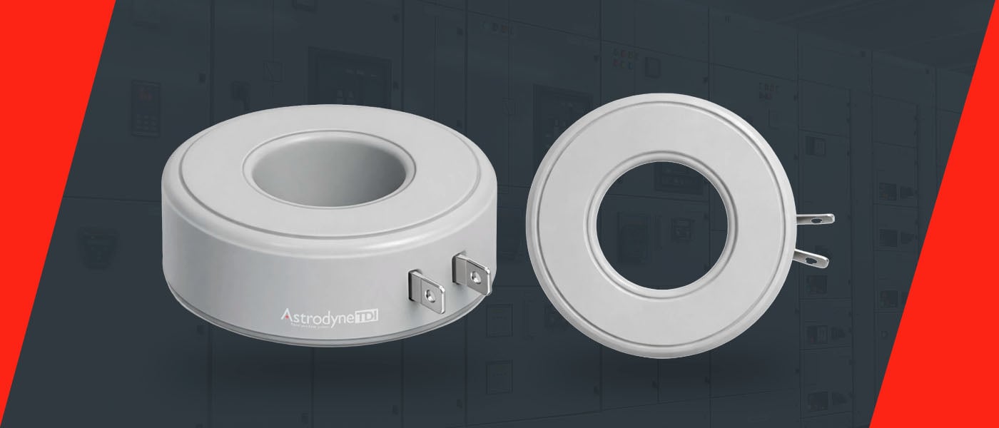
Different Shapes of CTs
Core geometry affects magnetic flux distribution and measurement accuracy. Circular construction minimizes flux concentration and harmonic distortion, making toroidal cores the preferred choice where accuracy and low noise matter most. Square cores accommodate split-core latching mechanisms.
Window Sizes
Aperture dimensions must accommodate conductor diameter, insulation thickness and installation clearance. Standard window sizes of 6.5 inches and 7.5 inches are common for handling busbars and cable bundles. Large conductors expand under thermal load, so engineers must allow enough clearance for temperature-related dimensional changes.
Technical Specifications for Selecting a High-Current CT
Ratio, accuracy class and burden rating determine electrical performance. Verifying these parameters ensures measurement precision and protection reliability within thermal and magnetic limits.
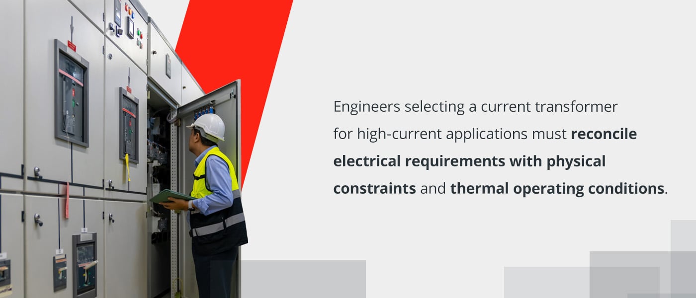
Engineers selecting a current transformer for high-current applications must reconcile electrical requirements with physical constraints and thermal operating conditions. Load profiles, fault levels and connected instrumentation all influence specification decisions.
Current Ratio
The transformation ratio defines the relationship between the primary current and the secondary output. Standard secondary ratings of 5A require primary ratings to be matched to the maximum continuous load. Correct ratio selection keeps core flux within the linear operating range.
Oversized ratios reduce secondary current below instrument sensitivity thresholds, and undersized ratios cause cores to saturate during normal peak loads. Saturation causes waveform distortion and measurement error. Engineers must account for continuous rating and short-term overload capability when specifying the ratio.
Accuracy Class
Measurement applications require tight error limits. International Electrotechnical Commission accuracy classes of 0.1, 0.2 or 0.5 suit revenue metering and precision energy monitoring. Protection applications tolerate higher steady-state error in exchange for improved saturation performance during faults.
Revenue metering demands compliance with utility billing standards. Protection functions prioritize magnetic headroom over steady-state precision. Dual-purpose units specify separate accuracy limits for metering and protection windings or accept balanced performance across both functions.
Burden (VA)
Connected meters, relays and wiring impose resistive and inductive load on secondary circuits. Total burden combines instrument impedance with cable resistance. Exceeding the rated burden degrades the ratio accuracy and introduces a phase shift.
Cable runs between transformers and panel-mounted instruments add a resistive burden. Engineers calculate burden by summing nameplate VA ratings of connected devices and adding calculated cable losses. Operating within rated burden maintains measurement accuracy and prevents thermal stress on secondary windings.
Why Insulation Class Matters for Reliability
The maximum operating temperature determines the insulation's service life. National Electrical Manufacturers Association standards indicate that Class B insulation withstands operating temperatures up to 130° C (266° F), and Class F insulation withstands up to 155° C (311° F). Elevated ambient temperatures, poor ventilation and high conductor heat combine to raise winding temperatures beyond nameplate ratings.
Operating above the rated temperature shortens service life and increases failure rates. High-current installations in enclosed panels or outdoor enclosures experience thermal challenges that exceed standard insulation capability.
The Limitations of Standard Class B Insulation
Many commercially available units are rated Class B. Winding temperatures in dense switchgear assemblies or poorly ventilated enclosures approach or exceed 130° C under continuous load. Under these conditions, insulation materials degrade and dielectric strength decreases.
Engineers installing transformers in confined spaces with limited airflow face the challenge of elevated operating temperatures. Outdoor enclosures exposed to direct sunlight add solar heating to conductor losses. Prolonged operation near their thermal limits reduces insulation life expectancy and measurement stability.
The Advantage of Class F Insulation for High-Heat Environments
Upgrading to Class F insulation adds 25° C of thermal margin. Windings tolerate higher continuous temperatures without accelerated aging. Class F current transformers can operate in environments that would degrade Class B units.
High ambient temperatures, densely packed panels and inadequate ventilation are common in modern industrial switchgear installations. Additional thermal capacity prevents premature failure, and measurement accuracy remains stable across temperature extremes.
Matching CT Construction to Your High-Current Application
Environmental conditions dictate construction type. For air-insulated panels and switchgear, encapsulated designs offer specific advantages in panel board applications. Film-insulated designs suit oil-filled transformers and bushings.
Encapsulated CTs
Epoxy or resin encapsulation protects windings from moisture, dust and mechanical damage. Heat dissipates through the encapsulant to the surrounding air, and the waterproof construction resists humidity and condensation in industrial environments.
Solid insulation provides mechanical strength and electrical isolation. Engineers choose encapsulated units where environmental protection and ease of installation outweigh weight or cost considerations.
Film-Insulated CTs
Engineers prefer film insulation systems for oil-filled transformers and bushing assemblies. Dielectric fluid provides cooling and additional insulation. Oil circulation removes heat more effectively than air convection, enabling higher continuous current ratings in compact designs.
Insulation materials must be compatible with transformer oil. Film-insulated designs are suitable for high-voltage applications where oil immersion is standard practice.